Caustics water texturing using Unity 3D
In this tutorial you will learn how to do real-time water texturing of caustics using the Unity 3D graphics engine. Even though this article is focusing on Unity 3D, the principles may be applied to other software as well.
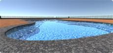
Take a look at the real-time pool demo or watch it on YouTube if you are curious on how the final result may look.
What is caustics?
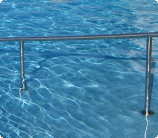
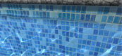
If you are observant, you may have noticed the dancing light patterns on the bottom of swimming pools during the summer. These light phenomena are in the computer graphics industry known as caustics. The caustics are caused by the convergence of refracted light in the water surface waves. If the water surface is quite calm, with small waves, these light patterns are more visible. This means that the phenomena may also be observed in lakes and the sea if the water is clear and there are not too rough water waves.
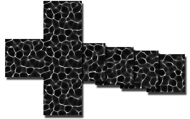
Calculating these light refractions is a time consuming process, especially if you are doing real-time graphics, so a common practice is to use pre-calculated caustics textures. The Caustics Generator software can be used to produce caustics textures that can be tiled and looped which is ideal for doing real-time graphics.
How do I use caustics textures?
The basic principle of caustics texturing is that you project the flat texture as light onto the geometry of your scene.
You can bake this process of light projection into the normal texture mapping of your objects if you are familiar with custom Shader programming. The standard shader in Unity 5 includes a texture slot called Emission. What it does is to add light emission to a surface using a texture, i.e. it brightens the object's basic texture based on the emission texture. The whiter the emission texture the brighter the basic texture will be.
UV-coordinate emission texturing using the Unity standard shader
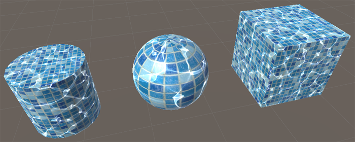
The problem with the emission slot of the standard shader in Unity 5 is that it is not actually meant to be used for projection, but rather for normal texturing using the UV-coordinates of the object. Thanks to Unity providing the actual source code for their shaders we can however modify their code and create a custom shader that does the job and provides a world-space parallel projection.
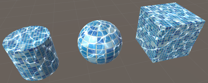
Projected world space emission texturing using a custom shader
Creating a projecting emission shader
The basic texturing of objects using the standard shader in Unity 5 is done in a file called UnityStandardCore.cginc. There are two functions that does the texturing; the fragForwardBase() and fragDeferred(). The first one is used when your camera is set to use the Forward rendering path and the latter when you use the Deferred rendering path.
The modification we are going to make to the emission part of the shader is the same for both rendering methods. It is the Emission() call in these functions that we are going to modify a bit.
Emission call in fragForwardBase()
Emission call in fragForwardBase()
We do not want to use the object's UV coodinates, i.e. the i.tex.xy expression, for our texturing. Instead we want to calculate a world space angular projection of the caustics texture. Let's take a dive into the code we need in order to do this.
World projected caustics texturing
This code includes a bit of more fancy stuff that enhances the caustics texturing, but we will go through it bit by bit to explain what is happening.
 // Caustics projection for texels below water level
if (s.posWorld.y < _CausticsStartLevel) {
...
}
// Caustics projection for texels below water level
if (s.posWorld.y < _CausticsStartLevel) {
...
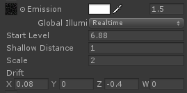
}As the comment says, we only want the caustics patterns to appear on the parts of the object that are below the water surface. We therefore introduce a variable called _CausticsStartLevel that is a world space Y-coordinate where the caustics will start appearing.
Wind affecting a water surface makes waves travel in the wind direction. To make the caustics look more natural we are moving the caustics patterns to simulate the surface movement. The _CausticsDrift is a world vector that sets the speed of the movement.
 // Fade out caustics for shallow water
float fadeFactor = min(1.0f,
(_CausticsStartLevel - s.posWorld.y) /
_CausticsShallowFadeDistance);
// Fade out caustics for shallow water
float fadeFactor = min(1.0f,
(_CausticsStartLevel - s.posWorld.y) /
_CausticsShallowFadeDistance);
In shallow water depths there aren't much caustics effects taking place due to the small convergence of light. We therefore introduce a fade distance from the Y-axis start level of the caustics. This also makes the texturing look smoother since there won't be a sudden start of the caustics where the water line breaks other geometry.
 // Remove caustics on half bottom of objects, i.e. no caustics "from below"
float3 upVec = float3(0, 1, 0);
float belowFactor = min(1.0f, max(0.0f, dot(s.normalWorld, upVec) + 0.5f));
// Remove caustics on half bottom of objects, i.e. no caustics "from below"
float3 upVec = float3(0, 1, 0);
float belowFactor = min(1.0f, max(0.0f, dot(s.normalWorld, upVec) + 0.5f));Another factor that is worth taking into account is the fact that light almost always comes from above. This means that the bottom of objects placed in water are not lit by caustics. We however extend around the edges of the bottom a bit with the +0.5 of the cosine value given by the dot operation in order to simulate that light may be coming in at an angle due to the water refractions.
The most important part of the whole texturing process is to calculate the world space projection of the caustics texture. We therefore take the world coordinate of the texel that is being calculated and rotate that texel using a light orientation matrix, which basically represents the direction of the incoming light. We will look later at how this matrix is being calculated. By taking the X and Y coordinates from the XY plane of the rotated texel coordinate we now have the texture coordinate for our caustics texture.
The final part of the whole process is to use the calculated texture coordinate and sample from the caustics texture using the original Emission() function. We then compensate for the fade and bottom factors which fade away parts of the caustics emission that we don't want.
Animation and light direction
The last missing part of the whole caustics texturing is that we need to animate the caustics texture because of the constant wobbling of the water surface. If we don't animate the texture it will look too static and not natural. The Caustics Generator software produces a sequence of animated frames that can be used for this purpose.
We perform the texture animation by adding a script in Unity to one of the objects that are using a material with our new shader.
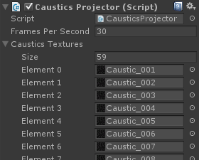
CausticsProjector.cs
The script simply replaces the emission texture with a new one at given intervals. As promised in the previous chapter we are here also providing the calculation of the light orientation matrix that was used for the projection calculation in the shader. If you don't want to constantly recalculate the light projection matrix you can paste a pre-computed one directly into your shader code.
Pre-computed projection matrix
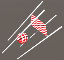
Why are we using a tilted projection matrix and not just a flat top projection in the Y-axis? Well, if you are doing terrain texturing it will be perfectly ok, and probably even best, to use a flat world-down-axis projection. However, if you are doing a swimming pool you also want caustics on the vertical walls of the pool. By tilting the projection angle you will get a nice projection even on the vertical walls.
Summary
Caustics texturing provides the final touch to all water rendering and it is a must for every modern simulation of water. What is provided in this article is a way of implementing it that does not add much extra cost to your rendering pipeline. A package containing the complete modified standard shaders for Unity 5 can be downloaded with the link below. You may freely use this code in your own Unity projects. The code in this article and the modifications to the standard Unity shaders are provided license free (Public Domain).
 Download complete Unity 5 caustics shader code